A comparator circuit compares two numbers and sets one of its three outputs to 1 indicating the result of the comparison operation. A Comparator circuit has multiple inputs and three outputs.
A 2-bit Comparator circuit compares two 2-bit numbers A and B. The comparator circuit has three outputs. It sets the A>B output to 1 if A>B. It sets the A=B output to 1 if A=B and sets A<B output to 1 if A < B.
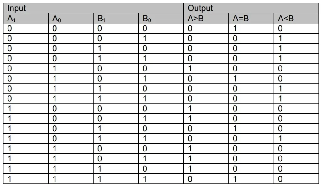
- The output A>B is set to 1 when the input combinations are 01 00, 10 00, 10 01, 11 00, 11 01 and 11 10
- The output A=B is set to 1 when the input combinations are 00 00, 01 01, 10 10 and 11 11
- The output A<B is set to 1 when the input combinations are 00 01, 00 10, 00 11, 01 10, 01 11 and 10 11
Related Posts:
The circuit has 4-bit input, 2-bits represent A and 2-bits represent B and a 3-bit output representing A>B, A=B and A<B. To represent the function of a Comparator circuit, three function tables are required for each of the three outputs. A single function table is drawn with three outputs.

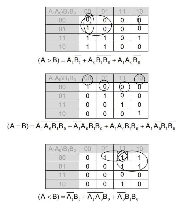
Each of the three outputs, A>B, A=B and A<B are mapped separately using three 4- variable Karnaugh maps. The Karnuagh Maps and the simplified expressions for the three outputs are shown.

