In this post, you will work with EWB’s test instruments.
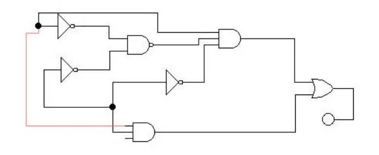
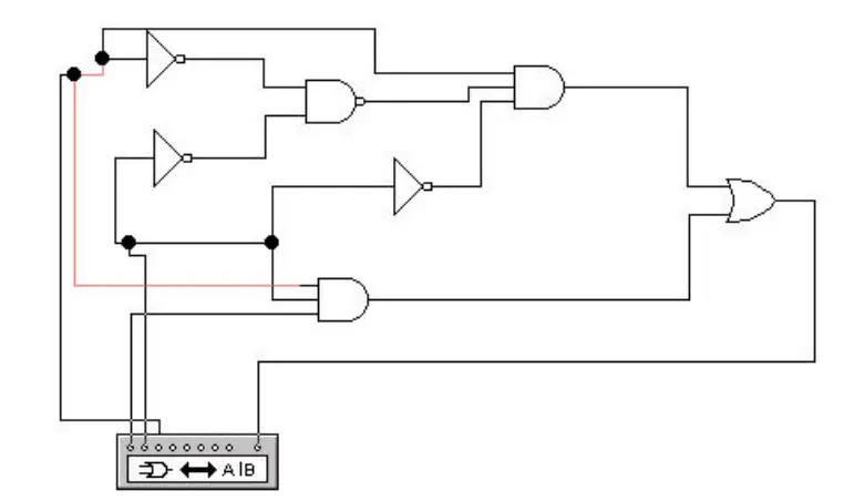
1. Create the following circuit on EWB’s circuit window.
Try Out Word Generator
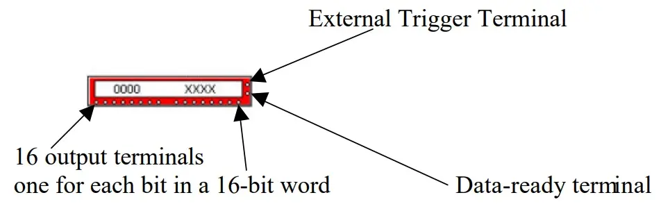
The word generator can drive a digital circuit by producing streams of 16-bit words. Use it to send digital words or patterns of bits into circuits to test them. The word generator icon looks like this:
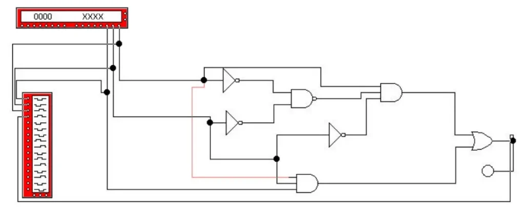
2. Attach a word generator to your circuit as indicated below. Double click on the word generator to open the word generator’s control.
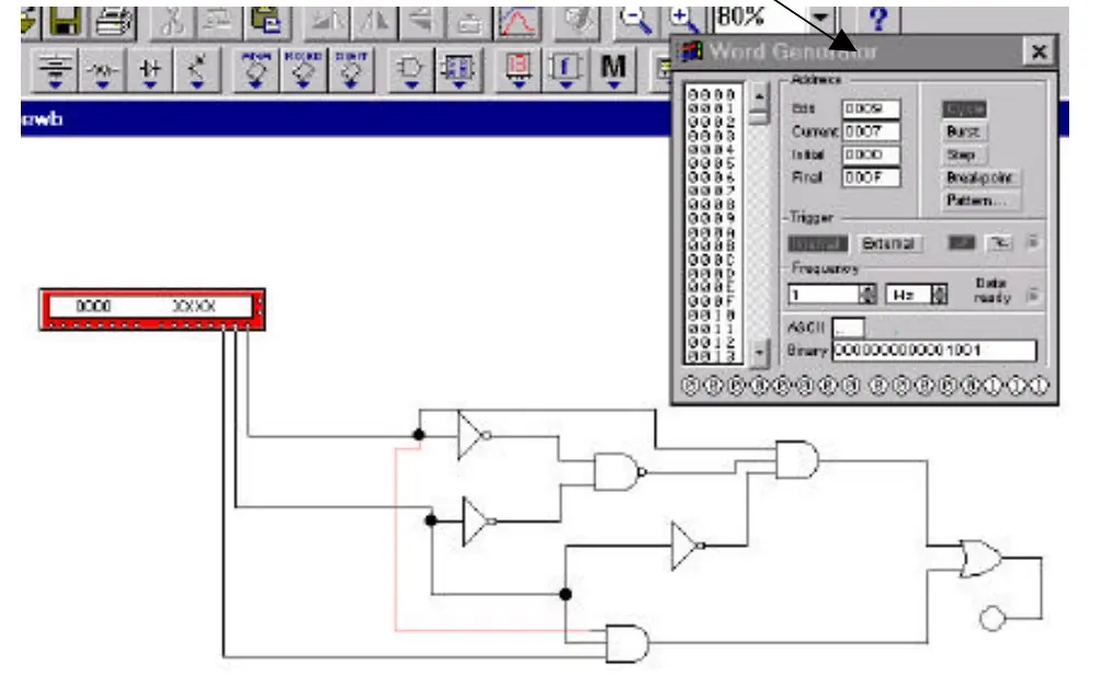
3. In the word generator control, set the frequency to 1 Hz, initial window to 0000, and final window to 000F. Click on the Pattern button and accept the Up Counter option. While watching the LED click the Step button on the word generator’s control. Try Burst and Cycle buttons as well.
4. Write the Boolean function for the circuit and verify its truth table using the previous step.
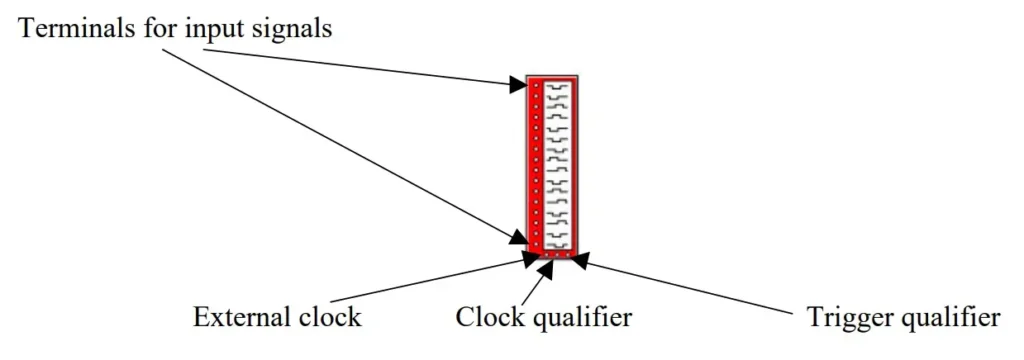
The 16-channel logic analyzer displays a circuit’s output as a waveform diagram showing voltage level and timing, similar to what you might observe on an oscilloscope attached to a circuit. The logic analyzer icon looks like this:
5. Attach a logic analyzer to your circuit as indicated below:
6. Double click on the logic analyzer to open logic analyzer’s window as shown below:
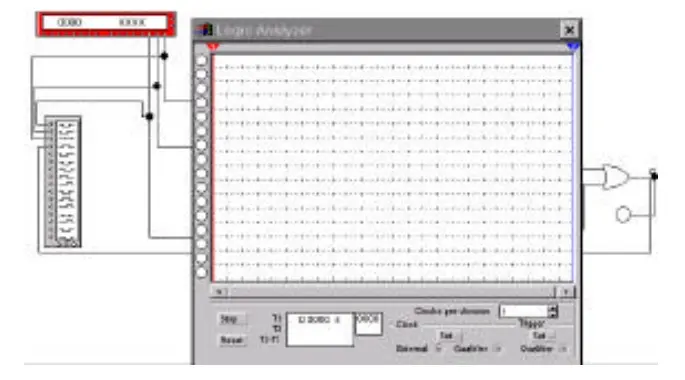
7. Set the clocks per division to 1. Next, click on Set button in the Clock area and set the Internal Clock Rate to 1 Hz.
8. Turn the power switch on and see the waveform on the analyzer’s window.
9. Verify the waveform with the truth table.
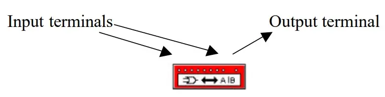
10. Attach a logic converter to the circuit as shown below:
11. Double click on the converter to open the logic converter window as indicated below. Click on this button to see the truth table for the circuit. Compare the truth table with yours.
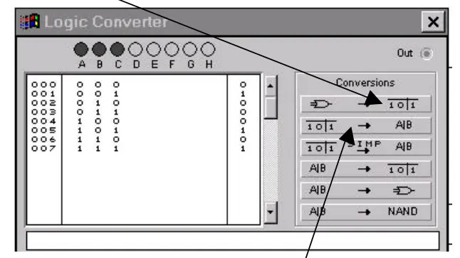
12. Click on the truth table to equation button to get the equation for the circuit.
13. Click on the truth table to simplified equation button (next button down) to get the
simplified equation for the truth table.
14. Try other features of logic converter. It can also be used to convert
- Truth table to a Boolean function.
- Boolean function to a circuit.
- Truth table to a circuit
Learn more about EWB: Introduction to Electronics Workbench