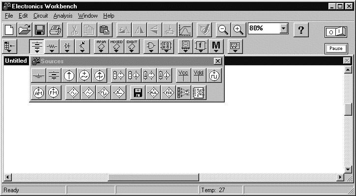
Introduction to Electronics Workbench
Electronics Workbench is an electronics and digital logic lab inside a computer, modeled after a real electronics workbench. It is a design tool that provides you with components & instruments to create “virtual” board-level designs:
- No actual breadboards, components, or instruments needed.
- Click-and-drag schematic editing.
- It offers mixed analog & digital simulation and graphical waveform analysis.
- Circuit behavior simulated realistically.
- Results displayed on multimeter, oscilloscope, bode plotter, logic analyzer, etc.
Using Electronics Workbench for Design
You may use EWB to:
- Explore ideas and test preliminary circuits.
- Refine circuits to full layout (If circuit requires parts of a previous design)
- Export files in format used by PCB (Printed Circuit Board) layout packages as move from design to production.
General EWB Functions
Selecting
- To move a component or instrument need to select it selected item highlights: components red, wires thicken
- Clicking to Select
To select single item, click on it. To select additional items, press CTRL+Click
- Selecting All
Choose Edit/Select All.
- Dragging to Select
Place pointer above & to side of group of items. Press & hold mouse button & drag downward diagonally. Release mouse button when rectangle encloses everything desired.
- Deselecting
To deselect single item, press CTRL+Click
To deselect all selected items, click on empty spot in window.
Setting Labels, Wiring
Setting Labels, Values, Models & Reference IDs,
- To set labels, values (for simple components) & models (for complex components), select component and choose Circuit/Component Properties, choose desired tab, make any changes, and click OK.
- Can also invoke Circuit/Component Properties box by double-clicking on component.
* Notes:
The Circuit/Component Properties box contains a number of tabs; depending on which component is selected an analog component has either a value or a model, not both.
- Point to a component’s terminal so it highlights; press & hold mouse button, and drag so a wire appears drag wire to a terminal on another component or to an instrument connection, when terminal on second component or instrument highlights, release mouse button.
Inserting, Connecting, Editing
Inserting Components
- To insert component into existing circuit, place it on top of wire; it will automatically be inserted if there is room.
Connecting Wires
- If drag a wire from a component’s terminal to another wire, a connector is automatically created when you release mouse button.
- Note: a connector button also appears in the Basic toolbar (to insert connectors into an existing circuit).
Deleting Wires
- To delete a wire, select it & choose Edit/Delete
- Alternatively, disconnect wire by selecting one end of it & moving it to an open spot on circuit window.
Changing Wire Color
- To change a wire’s color, double-click it & choose Schematic Options tab; click the Color button & choose a new color.
Straightening a Wire
- move wire itself.
- move component to which wire is attached.
- press ALT and move component to which wire is attached.
- select component and press appropriate arrow key to align it.
- If two wires cross in a way that makes them hard to follow, select one & drag it to new location
*Note:
– the way a wire is routed sometimes depends on terminal from which wire was dragged; try disconnecting routed wire & then rewire from the opposite terminal.
Instruments
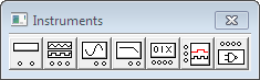
- Using an Instrument Icon
To display the Instruments toolbar, click the Instruments button on the Parts Bin toolbar.
To place an instrument on the circuit window, drag the desired button from the Instruments toolbar to the window. To attach an instrument to a circuit, point to a terminal on its icon so it highlights and drag a wire to a component. To remove an instrument icon, select it & choose Edit/Delete
- Opening an Instrument
Double-click the instrument’s icon to see its controls
- To selection options, click buttons on the controls
- To change values or units, click the up/down arrows.
Simulation

Click the power switch to turn power on. Click switch again to turn power off. (Note: Turning off power erases data & instrument traces.
Conclusion
I hope you like this post, and gained a lot of knowledge. I request you to do check more tools as well, and play with existing ones. You can download ewb 5.12 latest version button below:
Лучшие магазины
Выбор 3D принтера для промышленного использования
3д принтер промышленный prm-3dinter.ru .
Сравнение характеристик slm принтеров перед покупкой
slm принтер купить https://www.ptrlmms-3d.ru/ .
Top Picks and Reviews
portable solar generator for rv rv4sol-gen.com .
Sustainable Living
Renewable Energy Solutions for Mobile Homes: Solar Panels
Eco-Friendly Living with Solar Panels for Your Mobile Home
Upgrade Your Mobile Home with Solar Panels for a Brighter Future
Solar Panels: The Ultimate Energy Solution for Mobile Homes
solar panel kits for mobile homes http://www.larpan-mobi4omes.ru .
Charge Your Gear with Solar Power
Solar Panels for Camping: A Complete Overview
foldable solar panels for camping https://www.stport-solarpanels.ru/ .
Upgrade Your RV with the Best Solar Generator
solar generator for rv 30 amp https://www.argener-rv4.ru/ .
Где можно приобрести качественный 3D сканер
три д сканер купить три д сканер купить .
3D принтеры по металлу: цены на российском рынке
3d принтер металлом купить http://www.met3f-int43.ru .
3D принтер большого размера: что выбрать?
купить большой 3d принтер https://lastyu-bigpech.ru/ .