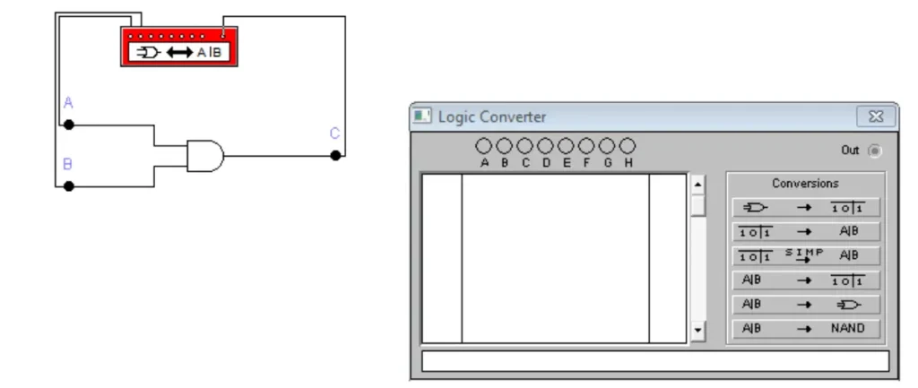
The logic converter can be found in the Instruments toolbox. It can be used to derive a truth table from a circuit schematic:
- Attach the input terminals of the logic converter to up to eight input points in the circuit.
- Connect the single output of the circuit to the output terminal on the logic converter icon.
- Click the Circuit to Truth Table button.

The truth table for the circuit appears in the logic converter’s display.
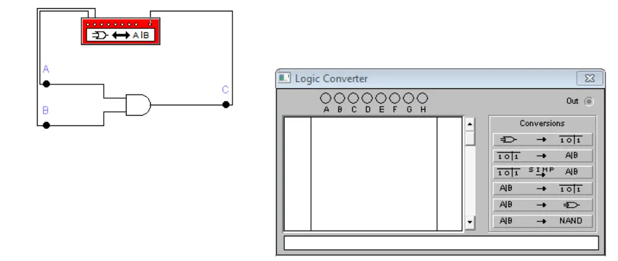
In the following circuit, we will be examining the AND gate. The two inputs of the gate are attached the A and B inputs of the logic converter. The circuit output C is connected to Outline of the logic converter.


