Electronics Workbench (EWB) is a design tool that provides you with all the components and instruments to create board-level designs on your PC.
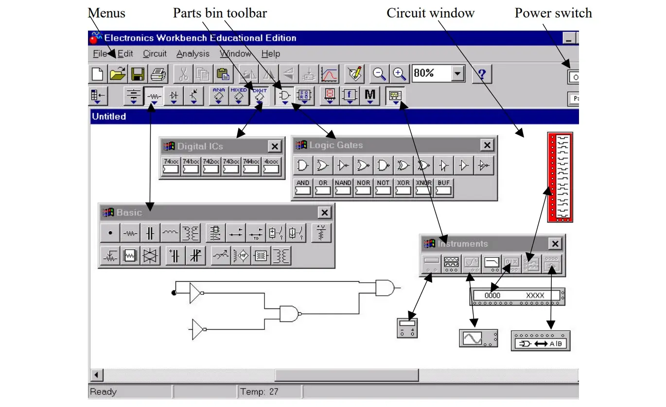
The user interface of EWB consists of the following:

The circuit window is where you create your schematics. The components and instruments that you need to construct a circuit are grouped into parts bins. Each parts bin has a corresponding button on the Parts Bin toolbar. Clicking one of these buttons displays another toolbar containing buttons representing the components and instruments contained in that parts bin.
To place a component or instrument on the circuit window, click the desired part button and drag the component or instrument to the circuit widow. Instruments toolbar includes a digital meter, a word generator, a logic analyzer, and a logic converter. These instruments may be dragged onto the circuit window and used to test the circuit that you build just as you would use test instruments in a lab. The final item on the menu bar is a power switch. You need to click on the power switch when you are ready to activate your circuit.
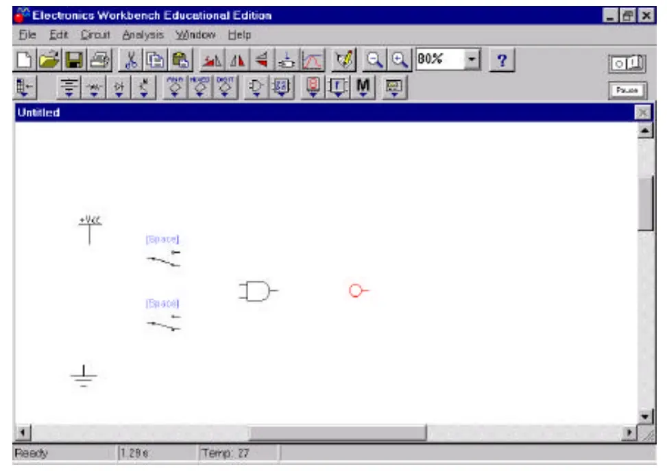
Tutorial Step 1:
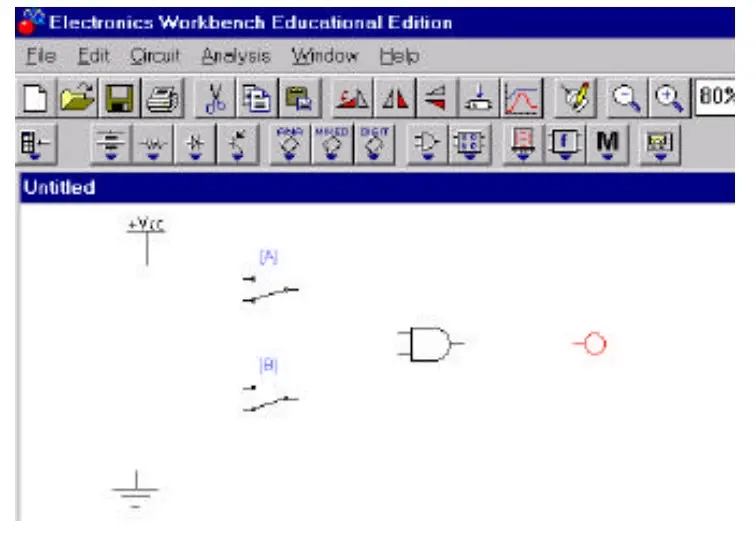
Find the following items from Parts Bin toolbars and place them in the circuit window as indicated below. Note that VCC represents +5 Volt.
To get information about a component or a test instrument, select it (by clicking the left mouse button on the component), and then press F1 key. You will see a help window with the information you requested. The following is an example of the help menu for a two-input AND gate.
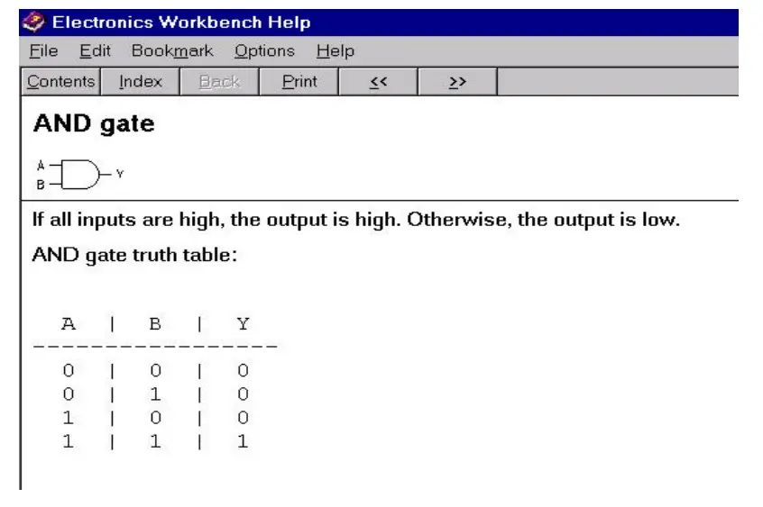
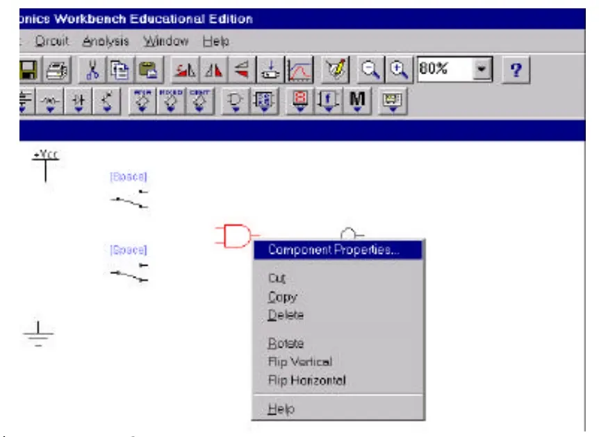
To set labels and values, or modify number of inputs or outputs of a component, select the component, click the right mouse button, and choose component properties. Note that the same menu can be used to rotate or flip the selected component.
Tutorial Step 2:
Label and rotate the components as indicated below:
To wire components together, press and hold the left mouse button, and drag it so that a wire appears. Drag the wire to a terminal on another component or to an instrument connection. When the terminal on the second component or the instrument highlights, release the mouse button. The wire is routed at right angle, without overlapping other components or instrument icons. If you drag a wire from a component’s terminal to another wire, a connector ⚫ is automatically created when you release the mouse button. A connector button also appears in the Basic toolbar. This let you insert connectors into an existing circuit, then drag another wire to one of its free terminals. Alternatively, you can place the connector on the circuit window where you plan to make a connection and drag wires to its terminals. You can join up to 4 wires with one connector.
Tutorial Step 3:
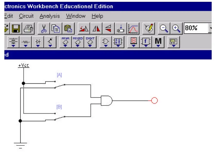
Wire components as indicated below:
Tutorial Step 4:
Using the mouse, click on the power switch to turn it on. Next, press combination of keys A and B to verify the truth table for the indicated AND gate.
In a complex circuit, colored wires can be distinguished more easily. To change a wire’s color, double-click it and choose Schematic Option tab. Click the Color button and choose a new color from the resulting dialog box.
To insert a component into an existing circuit, place it on top of a wire. It will automatically be inserted if there is room. If the not enough room for the component, it will remain on top of the component without being inserted.