7-Segment Display
The 7-segment display digit is shown below. 7-Segment Display is used to display the decimal numbers 0 to 9. A 7-segment display digit has 7 segments a, b, c, d, e, f and g that are turned on/off by a digital circuit depending upon the number that is to be displayed.
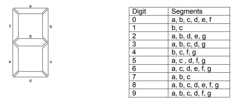
Different set of segments have to be turned on to display different digits. For example, to display the digit 3, segments a, b, c, d and g have to be turned on. To display the digit 7, segments a, b and c have to be turned on. The table indicates the segments that are turned on for each digit.
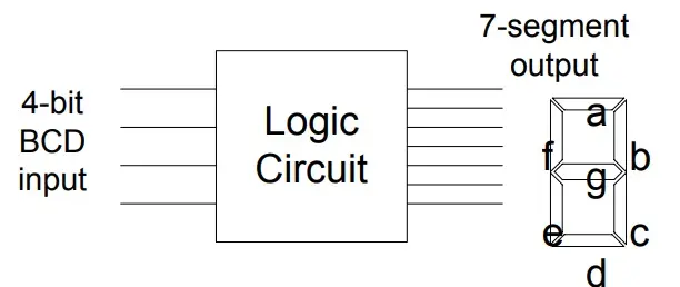
The circuit that turns on the appropriate segments to display a digit is known as a BCD to 7-Sement Decoder. The input to the BCD to 7-Segment decoder circuit is a 4-bit BCD number between 0 and 9. The seven output lines of the decoder connect to the 7 segments.
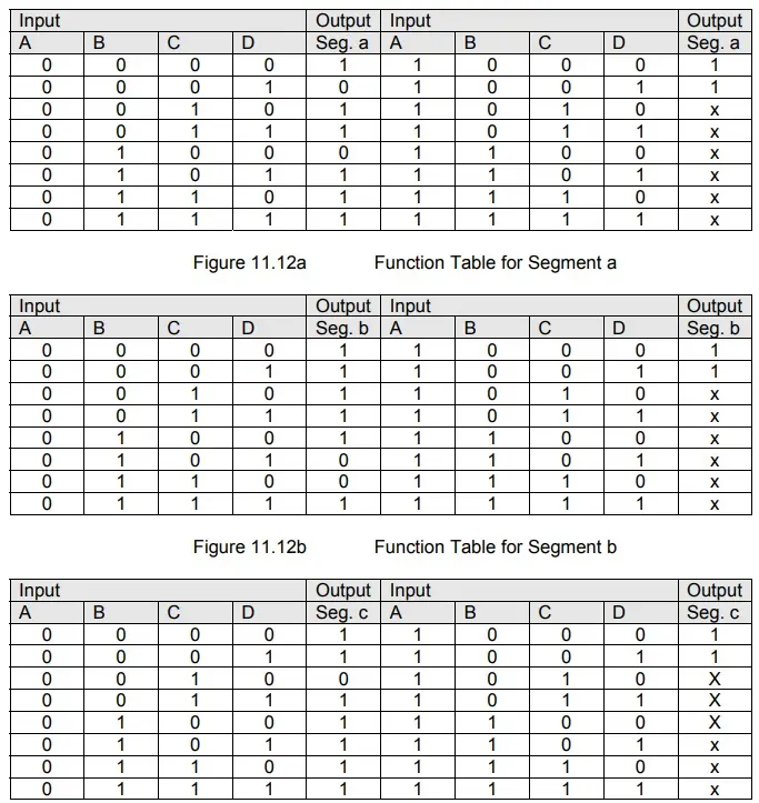
To implement the decoder circuit having 4 inputs and 7 outputs, function tables have to be drawn which represent the output status of each output line for all combinations of inputs. For example, the segment a is turned on when the 4-bit input is 0, 2, 3, 5, 6, 7, 8 and 9. Similarly, the segment b is turned on for 0, 2, 3, 4, 7, 8 and 9 combinations of inputs. Thus seven expressions, one for each segment has to be be determined before the decoder circuit can be implemented.
Related Posts:
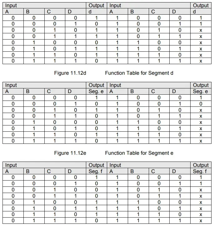
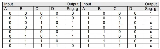
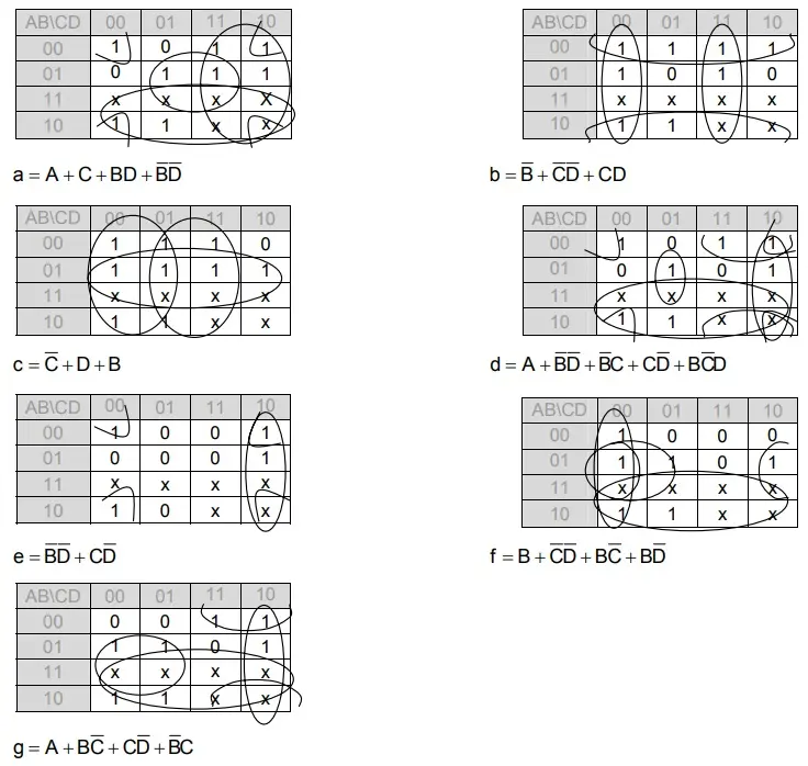
Seven function tables are required to represent the input/output combinations for each segment. The seven function tables for segments a, b, c, d, e, f and g are shown. To determine the seven expressions for each of the seven outputs, seven 4-variable Karnaugh maps are used. The Karnaugh maps and the simplified expressions are shown. An alternate way of representing the seven Function tables is to have a single function table with the four columns representing the 4-bit input BCD number and seven output columns each representing one of the seven segments a, b, c, d, e, f and g respectively.
Since the 4-bit input to the decoder circuit can have 16 possible input combinations, therefore each of the seven Function tables have sixteen input combinations. However, the last 6 input combinations are don’t care as these combinations never occur because the input to the circuit is a 4-bit BCD number. The don’t care states help in simplifying the Boolean expressions for the seven segments.
Function Table for Segment c
Function Table for Segment f
Function Table for Segment g
Karnaugh Maps and Simplified Boolean Expressions for Display Segments a to g
[…] What is 7-Segment Display? […]