Gray Code
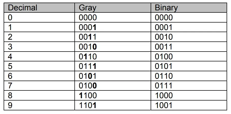
The Gray code does not have any weights assigned to its bit positions. The Gray Code is not a positional code. The Gray code is different from the unsigned binary code as successive values of Gray code differ by only one bit. Table 4.5 shows the Gray Code representation of Decimal numbers 0 to 9.

The bits in bold change in successive values of Gray code representation
Related Posts:
- Caveman Number System
- Finding the truth table of a gate using the Logic Converter
- Introduction to Electronics Workbench
Gray Code Application

The diagram shows a disk connected to the shaft of a rotating machine. The shaded areas on the disk indicate conducting area at a voltage of +5 volts. The non-shaded areas indicate a non-conducting area. Three stationary brushes A, B and C touch the surface of the rotating disk. The three brushes are connected to three LED lamps through wires. As the disk rotates the brushes come in contact with the conducting area and the insulated area. The three LEDs display the position of the rotating shaft in terms of 3-bit numbers. Thus if the disk on the right rotates in the anti-clockwise direction by 45^0 the Brush A comes in contact with the conducting strip at 5 volts, which turns on the LED indicating Binary 001.
If the disk continuous its rotation, after a rotation of another 450 , brush B comes in contact with the conducting strip and brush A comes in contact with the non-conducting strip. Thus LED connected to brush B lights up indicating binary 010. Thus at any instant of time, the LEDs indicate the angular position of the rotating shaft.
Assume that the three brushes A, B and C are not aligned properly and Brush B is slightly ahead of brushes A and C. Now if the disk rotates 900 from its start position. Brush A would be in contact with the conducting strip, Brush B due to its misalignment would also be in contact with the conducting strip and brush C would be in contact with the insulated strip. Thus when the disk rotates the LEDs will show a 001, followed by a 011 for a short duration when the disk rotates from 900 to 910 and then to 010. Thus due to misalignment the count value jumped from 1 to 3 and then back to 2.
Consider the disk shown on the right. The conducting and non-conducting strips follow a Gray Code pattern 000, 001, 011, 010, 110, 111, 101 and 100 representing decimal 0, 1, 2, 3, 4, 5, 6 and 7. Now even if the brushes are misaligned, the LEDs would always display the correct count value. Thus a Gray Code based shaft encoder allows angular position of the shaft to be determined even when the brushes are misaligned.
